This work is part and continuation of our previous work on Transverse Oscillations Techniques.
In order to perform fast (or ultra-fast) imaging, one needs to image a large field of view while decreasing the number of transmitted waves. One common way to achieve this is to produce plane waves by exciting all the probe elements at the same time. Since the image quality achieved with a single plane wave is suboptimal, several steered plane waves can be transmitted in a so-called compounding scheme. After a plane wave has been transmitted, the raw RF signals received by the probe elements must be coherently coalesced to construct the ultrasound image. One of the simplest methods is given by the delay-and-sum approach used by Montaldo et al.
There is another family of methods to recover images from the plane-wave-derived signals which works in the Fourie domain. The existing Fourier imaging techniques all show that it is possible to write a simple relationship between the 1D Fourier transforms of the raw RF signals received by each of the transducer elements and the 2D Fourier transform of the expected ultrasound image.
On the other hand, the 2D Fourier transform of a transverse oscillation image must clearly exhibit four identified “spots” whose positions correspond to the axial and transverse oscillation frequencies. We thus previously developed a filtering based transverse oscillation imaging “mode” which has shown to be able to produce images having four spots well defined in their 2D Fourier transform
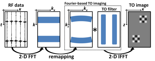
Fig 1: Formation of a TO ultrasound image by plane wave ultrasound imaging. Raw RF data are collected after a plane wave insonification (leftmost panel). They are then migrated (2 nd and 3 rd panels) in the Fourier domain : a 2D FFT of the raw channel signals is first performed, then the Fourier coefficients are remapped. A TO filter is used here (4 th panel) before the inverse Fourier transform to obtain a TO image of the medium (rightmost panel).
This technique
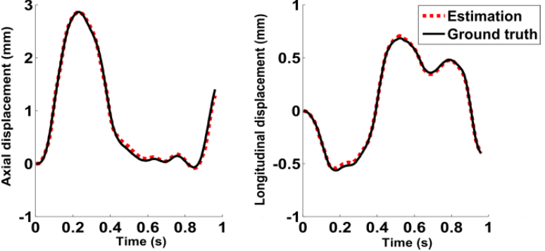
Fig 2: Simulation results. Ground-truth d (solid line) estimated (dotted line) displacements for both axial and longitudinal directions.
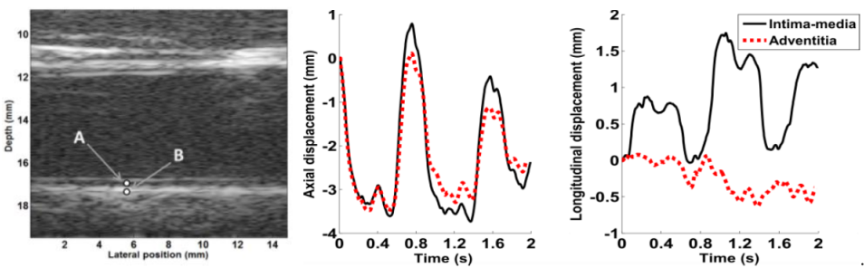
Fig 3: Experimental results obtained in vivo for two specific points A and B (see the reconstructed B-mode image). A is in the intima-media complex, and B is in the adventitia of the right common carotid artery of a healthy volunteer. The axial displacements are roughly similar (middle panel) for A (solid line) and B (dotted line). The rightmost figure shows that the longitudinal motion in the adventitia (dotted line) was close to zero, whereas large displacements were noticeable in the intima-media complex.Simulation results. Ground-truth d (solid line) estimated (dotted line) displacements for both axial and longitudinal directions.