Collaboration project between CREATIS and LabTau. This work was financially supported by the LabEx CeLyA (ANR-10-LABX-0060)
Context
Acoustic cavitation is a phenomenon which could be observed and used in many fields as hydrodynamic, chemical or biomedical engineering. It occurs when a high rarefaction pressure is locally applied. Bubbles nucleate and then collapse creating mainly mechanical damage. Among the large medical purposes, it plays an important role in the destruction of kidney stones in shock wave lithotripsy. Using the same principle, a new non-invasive innovative therapeutic technique called “Extracorporeal ultrasound thrombolysis” is being developed in LabTau. It focalizes high intensity ultrasound on the blood clot to destroy it mechanically. The therapeutic system is introduced in Fig. 1.
Passive imaging technique
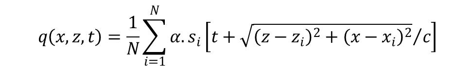
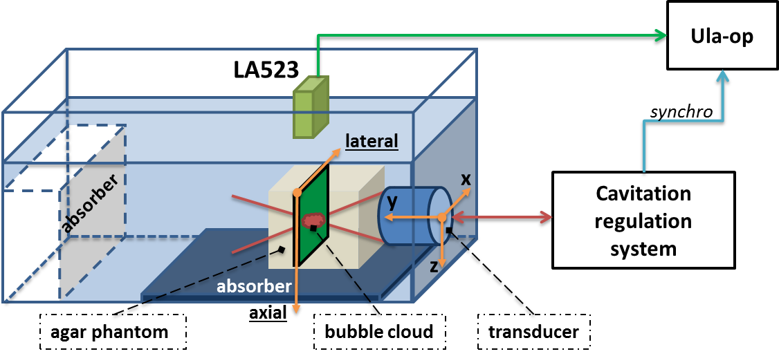
In CREATIS, we focus our work on developing a monitoring system which consists in tracking passively the ultrasound cavitation. The ultrasound imaging system (Fig. 2.) includes an Ultrasound Advanced Open Platform (ULA-OP) paired with a linear probe (LA523) which passively acquire radio frequency signals. These acquisitions are then post-processed in Matlab with a passive imaging beamforming method called PAM. It is inspired by the Delay And Sum (DAS) algorithm used in classical diagnostic medical ultrasound. An optimized version, called PAM-PCF, was implemented by adding a Phase Coherence Factor (PCF). [BOUL-16]
Preliminary results
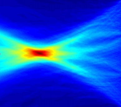
During a cavitation water tank experiment (Fig. 2.), the bubble cavitation cloud is induced at 70 mm from the imaging probe (LA523). Passive acquisitions are done and then the RF signals are computed thanks to both PAM and PAM-PCF beamforming algorithm. In Fig. 3. the two reconstructed cavitation map are shown. For quantitative interpretation, the acoustic pattern profiles in axial and lateral directions are plotted in Fig. 4.