Aim of the study
Beamforming is the name of signal processing techniques that combine raw data coming from an array of sensors in order to poudcue specific beam characterictics. In medical ultrasound there are numerous motivations to develop specific beamforming techniques, for example increasing the spatial resolution, the penetration depth, the signal to noise ratio etc..
At CREATIS-LRMN, research focuses on developping beamforming techniques in order to increase the accuracy of multi-dimensional motion estimation. This medical applications are elastography, cardiac motion estimation, or flow estimation.
CREATIS-LRMN is investigating beamforming techniques that lead to transverse oscillation (TO) images. The main idea of TO imaging is to create transverse modulation in order to increase the displacement estimation accuracy. Using those specific images with the appropriate displacement estimator
Transverse oscillations beamforming for motion estimation
In order to obtain TO images, different approaches can be used depending on the kind of data available for the beamformer.
Apodization in receive (ARX)
The first TO sequence designed uses a plane wave excitation, combined with dynamic receive focalization and apodization. Hence its name Apodization in receive (ARX)
$w_r(x_j)=1/2 ( e^{- \pi ( \frac{ x_j - x_0 }{\sigma_0} )^2 } - e^{- \pi ( \frac{x_j + x_0 }{\sigma_0} )^2 } )$ with $\sigma_0= \frac{\lambda_z z_P}{\sigma_x}$ and $x_0= \frac{\lambda_z z_P}{\lambda_x}$
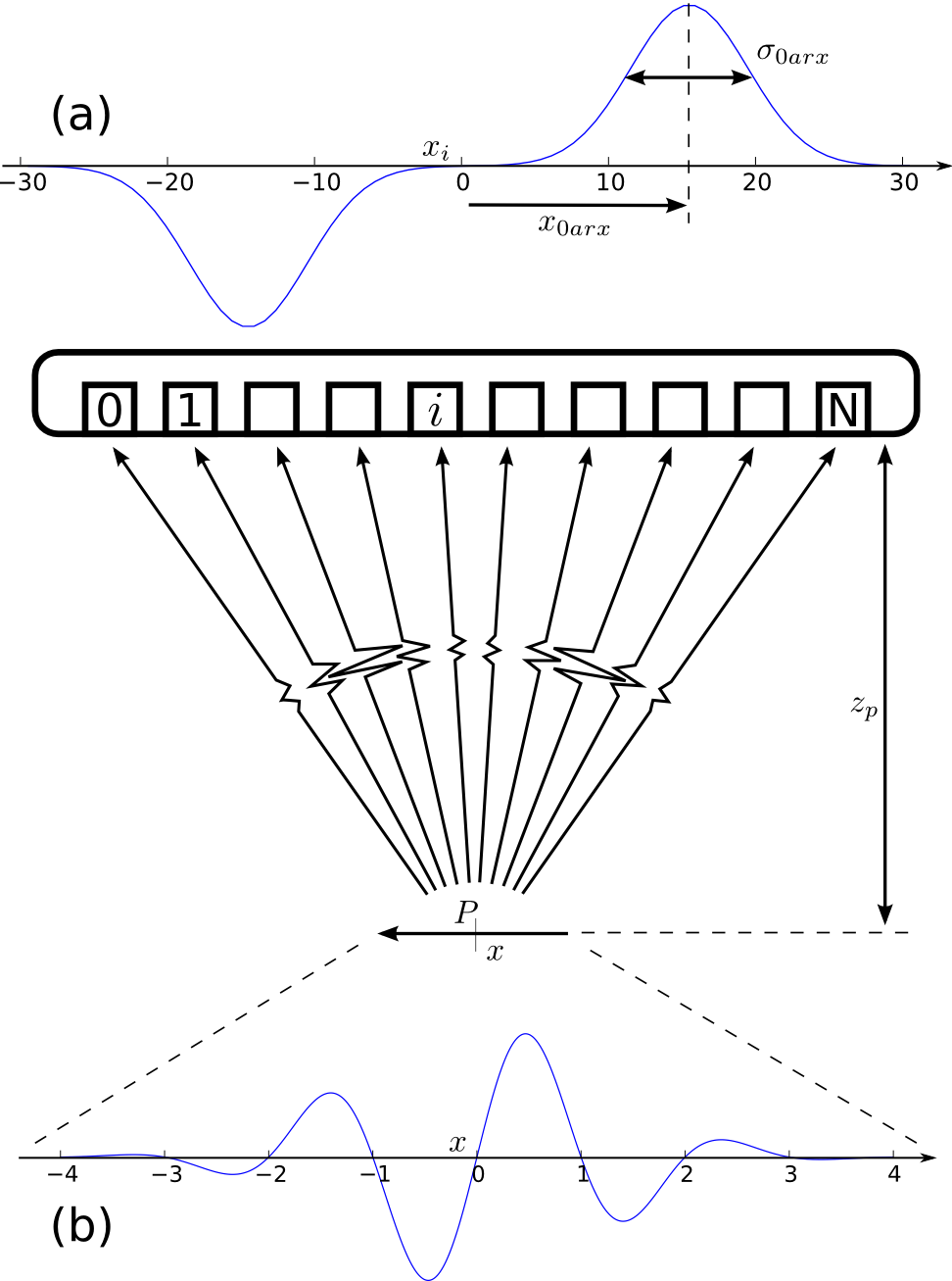 |
Figure 1 gives a overview of the ARX method. It shows the receive apodization window 1(a) and the resulting PSF profile 1(b) which feature modulation at the expected frequency. |
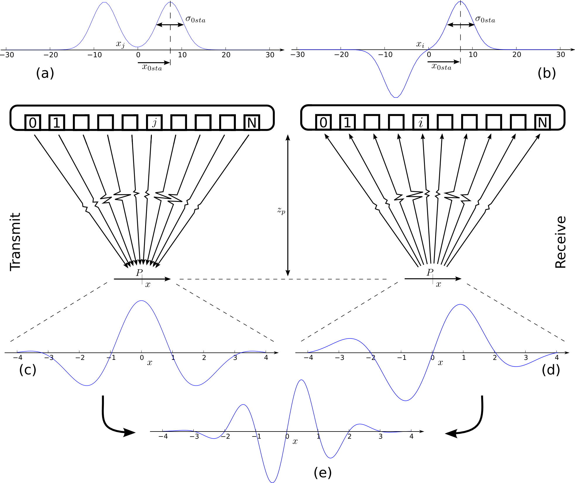
Synthetic aperture imaging (STA)
Synthetic aperture imaging (STA) is the second investigated technique. Compared to ARX, STA makes use of both transmit and receive apodization window. It also use dynamic focusing in transmit an receive. This leads to a more complex acquisition sequence but it allow the creation of higher transverse frequency modulation image for a fixed transducer size. During the acquisition, transducer element are excited separately and signals are received on each transducer element as well. It has also been shown to improve displacement estimation versus ARX
[math]w_t(x_j)=1/2 ( e^{- \pi ( \frac{ x_j - x_0 }{\sigma_0} )^2 } + e^{- \pi ( \frac{x_j + x_0 }{\sigma_0} )^2 } )[/math] [math]w_r(x_j)=1/2 ( e^{- \pi ( \frac{ x_j - x_0 }{\sigma_0} )^2 } - e^{- \pi ( \frac{x_j + x_0 }{\sigma_0} )^2 } )[/math] with $\sigma_0= \frac{\lambda_z z_P}{\sqrt{2} \sigma_x}$ and $x_0= \frac{\lambda_z z_P}{2 \lambda_x}$
 |
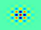
Experimental TO images
Acquisition and beamforming programs have been developed in the lab to create ARX and STA TO images. Its use a proprietary library made by Ultrasonix. the constructor of the lab ultrasound scanner.
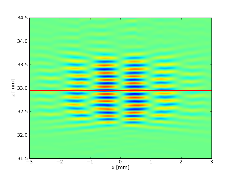
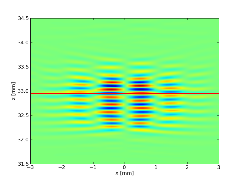
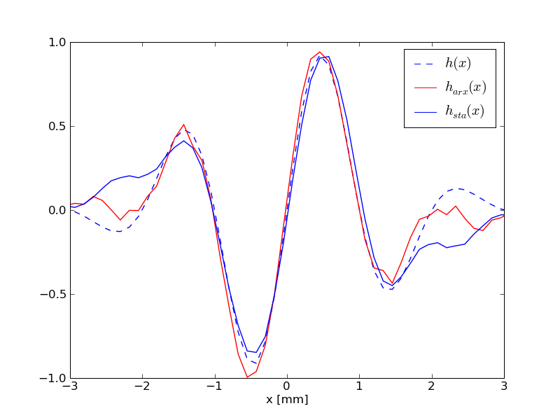
Here are interesting results of TO beamformed images. Figure 3 displays experimental PSF images for the ARX and the STA beamforming techniques as Figure 4 displays a movie of beamformed images for each techniques along with conventional images. The PSF profiles match well the expected one. The transverse modulation change the speckle shape and let displacement detail appear.